Please also note that these are images from multiple builds I've done in the past. I'm looking for the image that best shows what I'm describing in the instructions.
Please also note that you do this at your own risk. I will not be liable for any damage that may come from the steps below. Also you should know that doing this project will void any warranties you might have on your headlights. If you understand these risks - then feel free to proceed.
Anyways - lets get started.
What you need:
- A good set of headlights (I mainly use Eagle Eye Headlights)
- Good projectors (I normally use Morimoto Mini H1 7.
- Screw Driver (both Philips head and large flat head).
- JB Weld
- Window Weld (may not be needed - but good to have handy for later)
- Drill
- Cutting Tool
- Spray Paint (optional)
- Mechanics gloves (or grippy gloves you can use to handle a cooked hot headlight)
- Latex gloves
1- Remove extra parts from headlight
First thing to do is to remove all the parts possible from the headlights. If you have Eagle Eyes - then the following images will make sense. If you use a different brand - I think you will get the idea.Here is what needs to be removed:
- Bulb and locking ring
- Sealing ring
- Vent tubes
- 2 screws by the reflector
- 2 nails on the top of the headlight
2 - Cook Headlight
Once the headlight has all the parts removed, it is time to bake them.Set the Oven to 230 Degrees F.

3- Open Headlights
Once the oven is up to temp, Cook the headlight in the oven for 8 MinutesI recommend putting on Mechanics gloves and a old sweatshirt for the next part. The next step will be a little messy - so make sure the surface you are working on is clean but might get a little stained. I normally use cardboard or an old sheet over a table.
Alright - the time is here. Keep in mind the headlight is HOT at this point. Pull it out of the oven. There is one tab on the top of the headlight that needs to be undone and then carefully use the large Flathead screwdriver to pry the lens off the housing. Once you see it separating, keep working on prying open the side opposite of the reflector. I normally work that corner and the bottom, since there are two tabs that need to be separated down there. Keep prying and working on the corner of the headlight till you can get you fingers in to pry it open all the way.
While prying open, it is normal for the sealing material to spread like hot cheese. Try to cut it toward the housing. The main goal here is to keep the inside of the lens clean.
OPTIONAL instructions: If you do not intend to paint the reflector - then I recommend being careful to not let any sealing material to land in the reflector.
Once the headlight starts to open, the inside trim will more than likely stay with the lens. This is fine and good.
Once opened all the way, carefully place the lens to the side. Make sure it is in a safe area will the inside of the lens will remain clean.
4- Remove bulb Shield
Remove the bulb shield. There is a tab that needs to be pushed in and then the shield will slide out.

5- Remove reflector from headlight housing
Removal of the reflector is really only needed if you plan to paint the reflector. If you do not plan to paint the reflector, I'd recommend being extra careful in the cutting and drilling portions below. Wear latex gloves (or other type of gloves that will avoid leaving finger prints on the reflective paint).At this point, we need to remove the reflector from the housing. To do this I recommend first unscrewing the reflector adjustment screws from the housing. Once they are lose, carefully slide them off the reflector. The tabs on reflector are brittle, and will snap off rather easily. It is not a failed project if they do.
I do use a small screwdriver to help slide the clip thing off the reflector. Here are some images of the adjustment screws and how they connect to the reflector.


Once removed, this is what the removed adjust screws look like.


There are 3 mounting points. 2 of them are set up with the adjustment screws and a third is an anchored permanent post.
Once the reflector is removed, this is what the housing looks like.

6- Cutting and drilling
Cutting time! Take the reflector, and cut off the back end of the bulb cylinder lock. This cut is made to ensure we have the space needed to place a socket on the Projector nut when we are putting it all back together (step 9 below). It is just easier to get it dirty now since one of the next steps is to clean it for painting. Make the cut as shown in the images below:
Image above is how it looks stock.


Image above shows the cut.

Next - drill the hole for the High Beam cables (and optional demon eye LED cables). It is a good idea to have the cable handy so you can test fit if it will pass through the hole. Make it just large enough to ensure the cables that need to pass through, can fit through.

We have to also cut the projector shrouds now. I find it easiest to cut with a stout set of scissors. This cut should be on the bottom of the shroud. Which is the bottom part? Well, mount it to the projector. The cut off fence motor is on the bottom. I normally mark the cut with a sharpie before just to make sure I'm cutting off the right part. Please make sure you are doing the right cut - the shroud only fits on the projector one way.
Here is what the cut should look like:


7-Prepping for painting (optional)
If you want to paint the reflector and shroud, the next step is to strip the chrome off both parts.
I normally do this by scrubbing rubbing compound on them with a rag or sponge. This is what they normally look like after I've removed the chrome:


8- Painting (optional)
Ideally you want it somewhat scuffed up for the painting part - which comes next. I get some spray paint and put 4 light layers of paint on it. I do prefer flat black over glossy, but paint based on your preference. I buy paint designed for plastics and follow the directions on the can.

Let the paint dry and cure. Once done you are ready to put it all back together.
I strongly recommend you wear latex gloves for the rest of the process. At least until the headlight is sealed back up.
9- Mounting projector to the reflector
Remove the 3 screws that are holding the bulb backing plate in place. The shaft should look like the image below once the 3 screws and the plate are removed
Screw the shroud onto the projector. There should be 4 screws used. If you purchase it as a package from The Retrofit Source, then the screws are provided to you. Once completed, you should have the projector and shroud together like this:

On the back side - it is time to start getting it ready to mount to the reflector. Start by adding the larger (fatter) rubber gourmet to the back of the projector:


Then use the projector's Shaft Nut to bolt it all together. Hand tighten it. I have used needle nose pliers to do this, but have been most successful using a 28mm socket. I tend to score the nut if I use needle nose pliers. Please note if you are not adding demon eyes - the you probably will only have the red and black cables sticking out the back at this point.


10 - Mounting reflector back into the Headlight Housing
First thing is to slide the reflector onto the non-adjustable post. Easiest way to do this is to add the anchor to the post, and then slide the reflector into place.
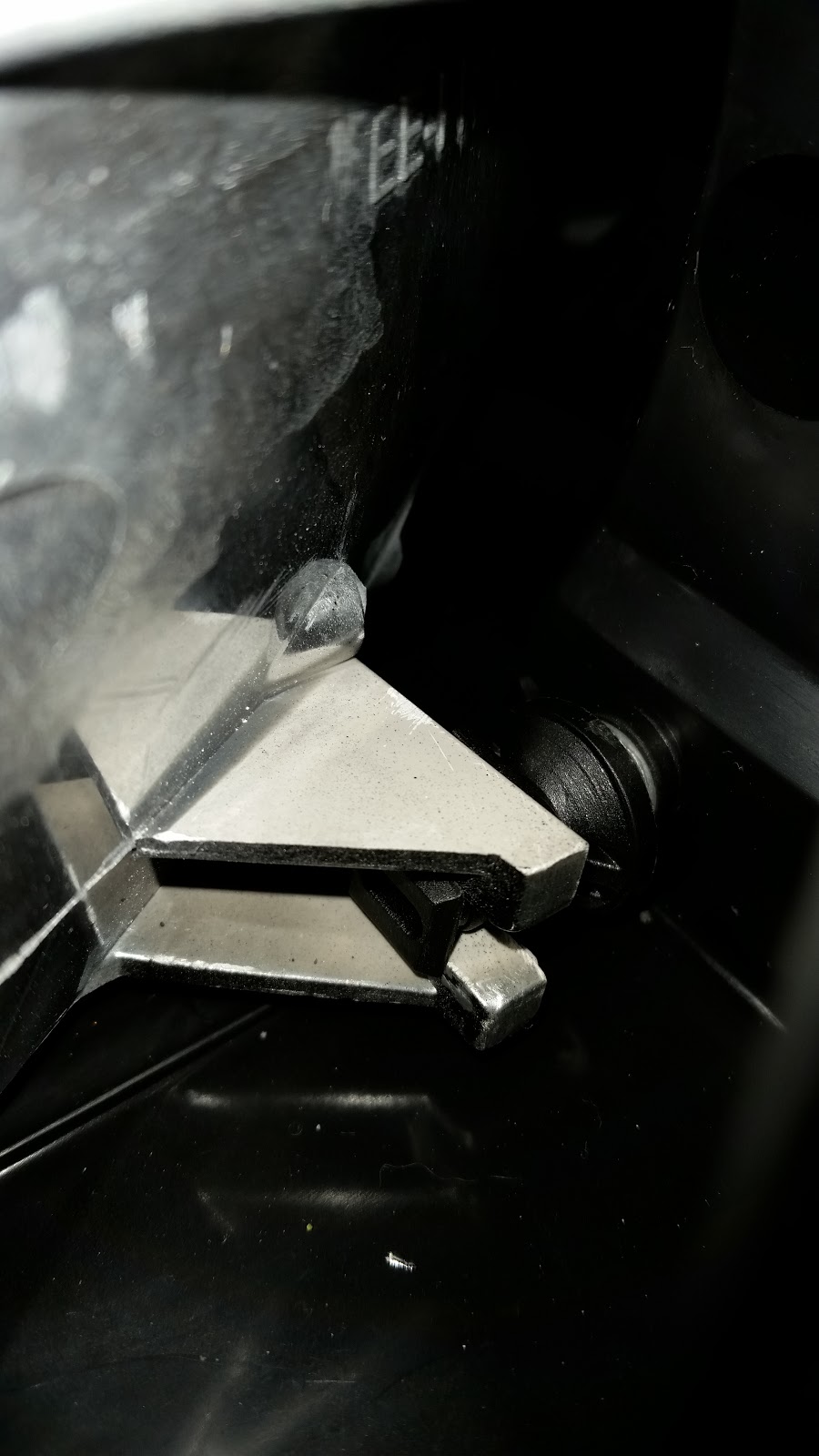
- Method 1 - Mount the adjustable posts to the headlight housing. Slide the anchors in place on the reflector, and then pop them onto the adjustable posts mounted on the headlight housing. BE CAREFUL to only put pressure on the anchor point as the tabs used to hold it in place on the reflector can easily break.


- Method 2 - Reverse order of method one. You place the anchors on the adjustable posts. Through the housing (without mounting them just yet) you slide the anchors into place. it is a bit more challenging that it looks. Once in place lock the adjustable posts into the headlight housing.


11- Reinforce the anchor points (also broken reflector tab repair)
WARNING: do not put any glue on the ball connection between the anchor and the studs they are mounted into. This glue should only touch the anchor and the reflector.
After building a few headlight like this - you learn where it breaks. It should be no surprise that adding the extra weight of a projector to a setup that was just designed to hold a bulb would potentially cause some issues. I'll tell you the weakest point are the reflector Tabs that hold the anchors and the anchors themselves. Once put together, these should not be moving so adding glue here will not impede the ability to adjust the light beam later.
Add JB Weld or glue to the anchor points. The glue should be such that it combines the 2 tabs as well as the anchor and makes it all into one piece.


Please also note that if you broke a tab in step 10, that this method is good to repair that break too.
12- Add the bulb backing plate back onto the projector
Pretty straight forward. Add the bulb backing plate that was removed on step 9 back in place. The plate should fit flush with the shaft. It should not be bending in any way.
The back and front should look like this right now:


13- Seal the holes we made in the back of the reflector
Use JB Weld to seal the holes we made in step 6. This will ensure the headlight is sealed properly and does not have condensation entering into it. Be careful though to not get any JB weld on the outer ring as it may make it hard for the back grommet to seal.


The seal made should be such that it ensures the cables are properly sealed.
14- Test the headlight - make sure it all works
In this step you need to make sure the projector works. If you have the high beam cut off, now is the time to test and make sure it all works right. I would plug it up to a 12V source and test it over an over again. At least 50 times. You really don't want to complete the next step and later find out it is not all right.
If you can get a bulb into the projector - you should test the beam now too. I've had bad projectors that have a soft cutoff line (mainly knock of projectors - never had an issue with Morimoto).
Also - to a small degree at least - test and make sure the reflector can be adjusted up and down, and left and right. I normally do the final adjustments in a later step - but now is the time to make sure it can be adjusted.
15- Seal it all back up
This is somewhat the same steps we had in steps 2 and 3, but in reverse. Heat up the oven to 230 degrees F.
On the headlight, put the lens in place as much as you can. You will normally need to get the reflector somewhat covered before the reflector corner part can properly come around and be put in place.
Once lens is in place, put the headlight in the oven and cook for 8 minutes.
- When you get the headlight out, you will need to focus on getting the reflector part of the lens pushed into the pocket in the headlight housing. This is very important.

- Once you feel that reflector corner is in place, then you can squeeze the lens into the housing so all 3 tabs lock it all in place. One of the tabs is on the top of the headlight and the other 2 are below.

- Once all 3 tabs are in place - try and add in the 2 small nails that were removed in step 1.
- Add the 2 screws back into place.


16- Cleaning up
At this point you probably have a little of sealant on the lens. This is normally the time point at which I clean it all off. I use Plastic-X as a lubricant to assist. I use a micro fiber cloth to polish the lens.


It can get a bit dirty. Also be warned that it may take a little extra elbow grease to get all the stains out.